(This is a project I did during the summer of 2023 that I’m writing about now.)
A pen plotter is a machine that moves a pen/pencil/etc. around under computer control to make drawings. A popular modern one is the AxiDraw by Evil Mad Scientist Laboratories. It comes in different sizes, with the largest being able to cover an A1 (841x594 mm) sheet of paper. But the price scales quickly with the size of the machine, and even the smallest model isn’t very cheap to begin with. What if you want to make really, really big drawings with your computer?
Instead of getting or making a machine that the drawing fits inside, we could figure out how the machine fits into the drawing. The machine would just do the part it can reach and then we would move it around to fill in the whole thing. Then we would be able to make drawings of any size (as long as we don’t exceed our means of finding where the machine is).
I’ve long had this basic idea bumping around in my head. Many years ago I first gave it a shot using the Lighthouse tracking from the Vive VR system and an AxiDraw:
It was very rough but it proved the concept. I just zip-tied the Vive controller onto the AxiDraw and didn’t do anything to properly find its actual pose relative to the plotter, so the accuracy was poor. And then I got distracted by some other work and the idea receded into the back of my head, until…
In 2023 I was working a lot on digital fabrication tools for artists, and part of that involved playing with the AxiDraw again. We were building various bespoke tools like extruders, chalk/charcoal/pastel spinners, vibratory dispensers, etc. which all had actuators which could be controlled in different ways to affect the output (e.g. on/off or slower/faster). I was curious if there was a way to put those types of tools on the AxiDraw and control them.
The AxiDraw has a control board on it which was originally designed for a plotter meant to draw on eggs called Eggbot. It was reused for the AxiDraw and given the more generic name “EiBotBoard” (EBB). It turns out that this board has a lot of extra capability that goes unused in the AxiDraw, but it’s still accessible via the serial protocol used to tell it what to do. There’s a nice documentation website for this protocol. While reading that I saw commands for interacting with the general purpose I/O pins exposed on the EBB. That means it can be used like an Arduino for physical computing purposes. For example, turning LEDs on or off, driving additional servo motors, or reading the value of various sensors.
Mostly the AxiDraw (and all plotters, and digital fabrication tools in general) are used as pure output devices. A person makes a design in the computer and then sends it to the AxiDraw to follow 1:1. But I believe that there’s a lot of potential in making tools that adjust what they’re doing as they work, on their own or in response to live human input. My favorite example of what that can lead to is the painting work of my friend Jeff Leonard.
So when I saw that there was this untapped I/O on the AxiDraw I wanted to make it available for people to use for that kind of thing. Or just to make it easier to attach and control new kinds of active tools like the ones I mentioned above. I ended up writing a library for p5.js called p5.axidraw. It uses WebSerial to control the AxiDraw from your browser. The basic movement and pen controls are exposed there. But it also has the ability to read and write to those extra I/Os on the EBB.
After I had p5-axidraw working well enough I started to play with it. One early experiment I did was turn the AxiDraw into a scanner by attaching a light sensor and LED:
While thinking about the light sensor I remembered my old project with the AxiDraw and the Lighthouse tracking system. I realized that there was a way to do a similar thing just by using the light sensor in combination with a projector via a technique called “structured light”, where you project the information needed for localization into the environment.
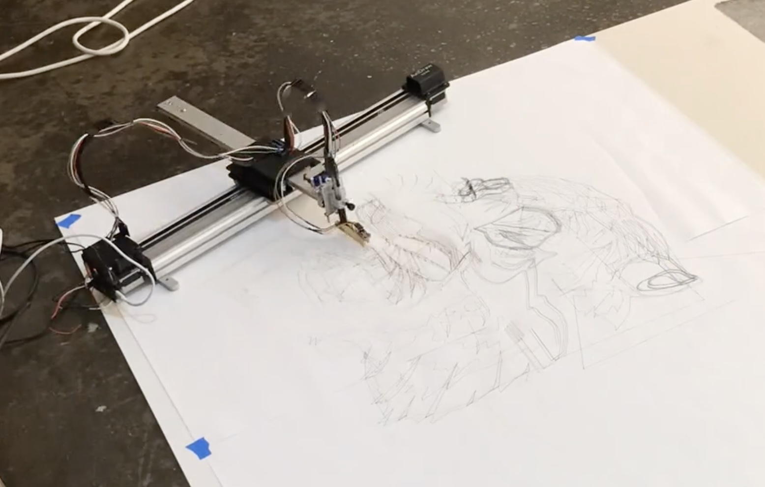
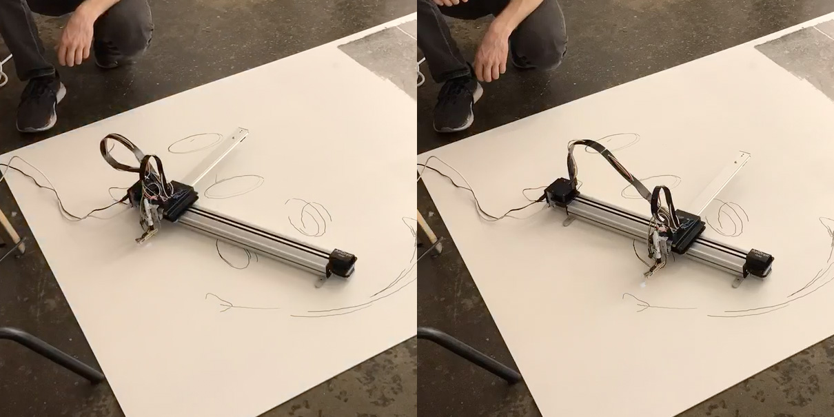
The basic idea is to attach a light sensor to the AxiDraw so that it can sense the amount of light coming from above:
Sadly I didn’t take any close-up pictures of how I attached the light sensor so you’ll have to squint at the cropped video frame above. I hot-glued the light sensor on the end of a clothes pin (a scissor-style wood one) and then clamped it to the sharpie marker that I used to draw. This got it close to the drawing surface, which was helpful for the next steps, but it also added a small offset to the tool that I had to measure and subtract.
Once you have the sensor attached you can point a regular digital projector at the area where you want to make your big drawing and put the AxiDraw down somewhere in that area. Now if you were to project a small white square and it happened to light up the sensor you could read the sensor value and know that the sensor is somewhere inside the white square in the projected image space. It’s just a single point so you don’t know how the AxiDraw is rotated or how much area it can reach (the scale). But if you have the AxiDraw move the light sensor by a known distance and find it again the same way you can use those two points to figure out the rotation and scale.
At that point you know the 2D pose of the AxiDraw inside of the overall projected image. So you can take your big drawing and slice out just the part that the AxiDraw can reach from there and have it draw that. Then just pick up the AxiDraw and put it down in an unfinished area of the drawing and repeat to complete the whole thing.
I left out one key step, which is how we find the light sensor with the white square. You could imagine just sliding it in a raster pattern from left to right and top to bottom, stopping when the light sensor detects it. But that’s pretty slow. We can speed things up immensely by using a binary search. All we have to do is light up one half of the current region at a time and see if the light sensor detects a change. When we see the light we know the sensor is in that half, so we call that the new current region and recurse. At every step we reduce the area where the light sensor could be by half.
With that we have all the basic ingredients to make this work. I decided to start by making a pure software prototype in p5.js, which looked like this:
It puts the simulated AxiDraw down at a random location and position. Then it does the binary search with the projected light twice to find 2D the pose of the AxiDraw. Then it simulates the drawing process. The process repeats forever, slowly filling in the image.
Here’s what it looks like sped up:
Trying it in real life brought a few extra difficulties. The ambient light interfered with the sensor readings, and the difference between when the projector was shining on the sensor and when it wasn’t was not as big as I had hoped. I couldn’t make the space where I was working any dimmer so I just had the code look for smaller differences. As a result it started to erroneously detect the projected light, which would make the search process get stuck. So I made it able to back out to a wider search area if it didn’t see a light change in either half. I also had to find a reasonable minimum size for the projected squares which was as small as possible but still big enough to be seen by the sensor.
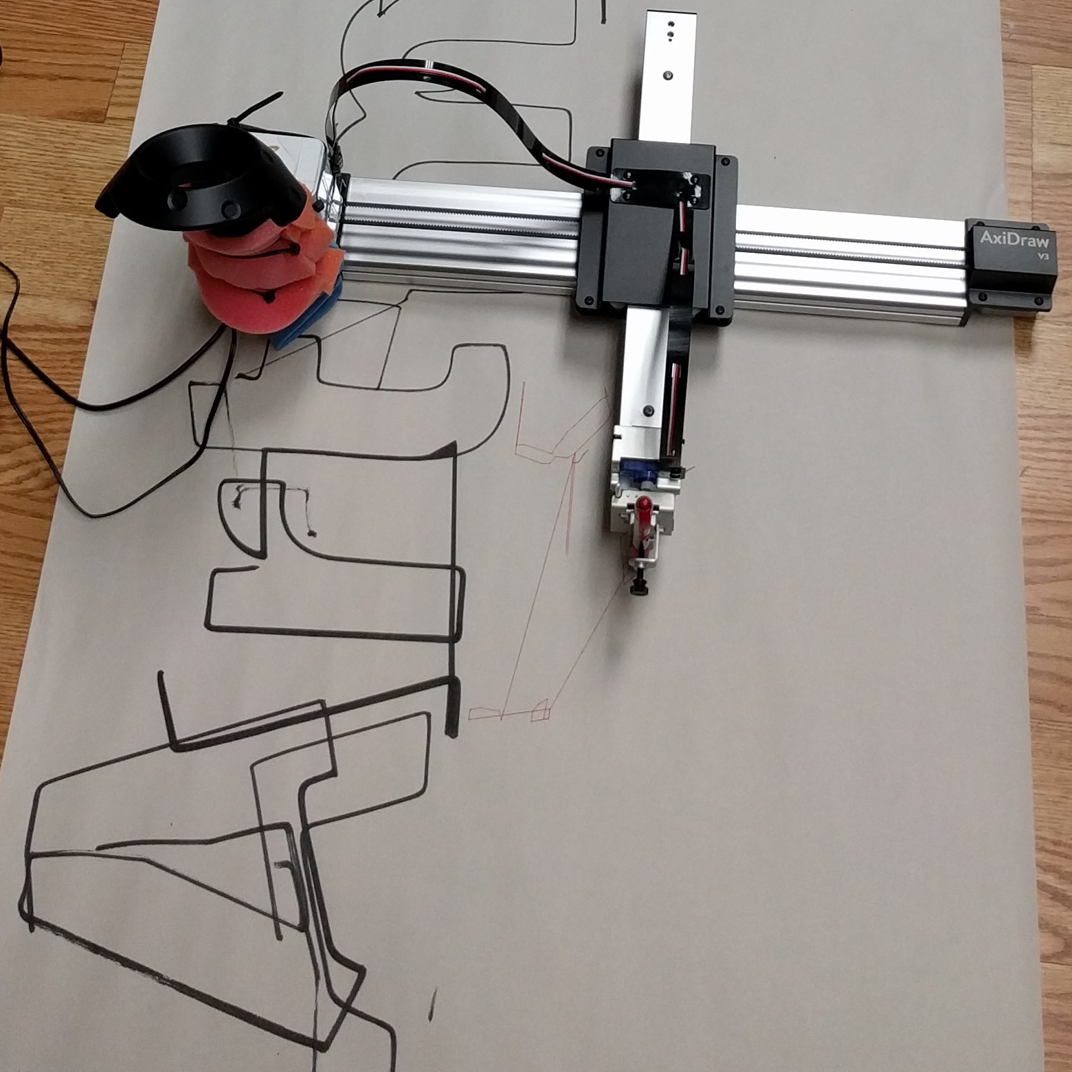
In the end I got it working!
Plotting the Ghostscript Tiger:
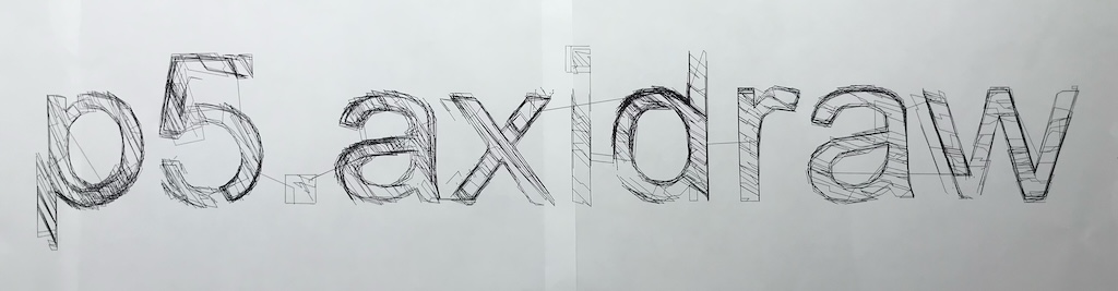
Plotting a banner for the p5.axidraw library:
Here’s the final p5.js sketch: Plot by Projection
Comments
To leave a comment, you need an Are.na account. Comment on this post’s Are.na block and it will appear here.